 |
Clustered dot ordered dither
In order to generate the spots in a clustered dot dithered image, a
grid is super-imposed on the original image.
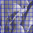 Fig 1: 16x16 grid over the image
The image is divided into cells by the grid - each cell will
ultimately hold a single spot made up of multiple device pixels
in order to approximate the darkness of the original image in that
cell.
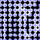 Fig 2: image after dithering
As you can see, a large cell size results in a heavy loss in
resolution! Note also that the spots in the cells start off as
circles, and grow to be diamond shaped. This change in shape is
controlled by a spot function. By using different spot
functions, the evolution in the shape of the spots as the cell goes
from fully black to fully white may be controlled.
 Fig 3: reference greyscale gradient
 Fig 4: Euclidean dot, 0° screen angle
Figure 4 displays the Euclidean spot function as the tone changes from
black to white. Notice how these spots are clearly defined compared
to the slightly smudged look of those in Figure 2 above. This is
because the spot function defines a threshold value for each pixel in
the cell, and this threshold value is compared against the image to
discover what the output device pixel should be. The output pixel is
illuminated only if the image's pixel is above the threshold. This
means that sharp edges in the image are not lost, but the spots are
less regular. In practice, the cell sizes used here are rather large
in order to emphasise these effects; normally they are less
perceptible.
The Euclidean dot is not the only spot function available. The merits
and detractions of a variety of spot functions are covered on the spot function reference page.
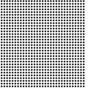
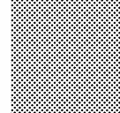
So far, the screen has been aligned with the horizonal and vertical
axes. It turns out that the human eye is very good at discerning
horizontal and vertical lines, but the screen should ideally have the
minimum impact on the image possible. This is the reason that screens
aligned to 0° (or equivalently 90°) are not normally used by
themselves, whereas 45° is favoured as being minimally visible:
 |
 |
|
(a) 0° screen
|
(b) 45° screen
|
Fig 5: screen angle and visibility
In fact any screen angle may be used, with positive angles being
anti-clockwise rotations, as demonstrated by Figure 6.
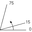 Fig 6: screen angles increase anti-clockwise
[ On to spot reference . . . > ]
(c) 1998 Austin Donnelly <Austin_Donnelly@yahoo.co.uk>
$Id: clustered-dot.html,v 1.4 2001/05/25 12:25:46 and1000 Exp $
|


